Scenarios
If the number of network interfaces attached to an instance exceeds the upper limit, you can attach supplementary network interfaces to the network interfaces, including the primary and extended network interfaces, of the instance. This helps you set up flexible and highly available networks.
Notes and Constraints
- Supplementary network interfaces must be in the same VPC as the network interface they are attached to, but they can be in different subnets and security groups.
- After supplementary network interfaces are created, you need to create VLAN subinterfaces on the network interface of the instance and configure corresponding rules by referring to Configuring a Supplementary Network Interface.
Creating a Supplementary Network Interface
- Log in to the management console.
- Click
 in the upper left corner and choose Network > Virtual Private Cloud.
The Virtual Private Cloud page is displayed.
- In the navigation pane on the left, choose Virtual Private Cloud > Network Interfaces.
- In the upper right corner of the page, click Create Supplementary Network Interface.
- Configure the parameters based on Table 1.
Table 1 Parameter descriptions Parameter
Description
Example Value
Region
Region where the supplementary network interface will be created. Select the region nearest to you to ensure the lowest latency possible.
-
Network Interface
Network interface that you want the supplementary network interface to attach to.
Select an elastic network interface from the drop-down list.
--(172.16.0.145)
VPC
VPC where the supplementary network interface will be created. The VPC of the network interface that the supplementary network interface is attached to is selected by default.
vpc-A
Subnet
Subnet where the supplementary network interface will be created. The supplementary network interface and its network interface can be in different subnets.
subnet-A01
Quantity
Number of supplementary network interfaces to be created.
1
Private IP Address
Whether to assign a private IPv4 address or IPv6 address to the supplementary network interface. There are two options:
- Private IPv4 network: a private IPv4 address will be assigned. This option is selected by default and cannot be deselected.
- IPv6 network (Public and private network traffic): a private IPv6 address will be assigned. Both private and public IPv6 networks are supported.
IPv6 is shown only when IPv6 is enabled for the subnet of the supplementary network interface.
IPv4
IPv4 Address
How a private IPv4 address will be assigned to the supplementary network interface. There are two options:
- Automatically assign IP address: The system assigns an IP address from the subnet you have selected.
- Manually specify IP address: You can specify an IP address.
If you select Manually specify IP address, enter a private IPv4 address.
Automatically assign IP address
IPv6 Address
How an IPv6 address will be assigned to the supplementary network interface if IPv6 network (Public and private network traffic) is selected for Private IP Address.
There are two options:
- Automatically assign IP address: The system assigns an IP address from the subnet.
- Manually specify IP address: You can specify an IP address.
If you select Manually specify IP address, enter an IPv6 address.
Automatically assign IP address
Security Group
Security group that the supplementary network interface will be associated with.
sg-001
Description (Optional)
Description of the supplementary network interface.
The description can contain a maximum of 255 characters and cannot contain angle brackets (< or >).
-
- Click Create Now.
To use a supplementary network interface, you need to create a VLAN subinterface. For details, see Configuring a Supplementary Network Interface.
Configuring a Supplementary Network Interface
After a supplementary network interface is created, you need to create a VLAN subinterface for the network interface of the instance and configure a private IP address and default routes for the supplementary network interface.
Before doing so, you need to obtain:
- The information described in Table 2 when you configure a supplementary network interface for a Linux ECS.
- The information described in Table 2 and Table 3 when you configure a supplementary network interface for a Windows ECS.
Table 2 Information about the supplementary network interface and subnet Item
How to Obtain
VLAN ID
- In the supplementary network interface list, click the private IP address of the target supplementary network interface.
The Summary page is displayed.
- On the displayed page, check and record the following information:
- VLAN ID
- MAC address
- Private IP address
MAC address
Private IP address
Subnet mask
- In the supplementary network interface list, locate the target supplementary network interface and click the subnet name in the Network column.
The Summary page of the subnet is displayed.
- On the displayed page, check and record the following information:
- Subnet mask: subnet mask of the IPv4 CIDR block. For example, if the IPv4 CIDR block is 192.168.0.0/24, the mask is 24.
- Subnet gateway: In the Gateway and DNS Information area, check the gateway address.
Gateway address
Table 3 Information about the network interface and subnet to which the supplementary network interface belongs Item
How to Obtain
MAC address
- In the ECS list, click the name of the ECS with the network interface attached.
The Summary page is displayed.
- Switch to the Network Interface tab and click
 to check and record the following information:
- MAC address
- Private IP address
Private IP address
Subnet mask
- In the network interface list, locate the target network interface and click the subnet name in the Network column.
The Summary page of the subnet is displayed.
- On the displayed page, check and record the following information:
- Subnet mask: subnet mask of the IPv4 CIDR block. For example, if the IPv4 CIDR block is 192.168.0.0/24, the mask is 24.
- Subnet gateway: In the Gateway and DNS Information area, check the gateway address.
Gateway address
- In the supplementary network interface list, click the private IP address of the target supplementary network interface.
Configuring a Supplementary Network Interface for a Linux ECS
The following describes how to create a VLAN subinterface for a supplementary network interface of an ECS network interface. CentOS 7.8 is used as an example. In this example, the information about the supplementary network interface and subnet is as follows: This example describes how to configure the supplementary network interface for the primary network interface of an ECS. If you want to do the same thing for the extended network interface of the ECS, follow the similar steps.
- Log in to the ECS.
- Run the following command to check and record the network interface name of the ECS:
ifconfig
Information similar to the following is displayed. In this example, the network interface name is eth0.
[root@ecs-subeni-linux ~]# ifconfigeth0: flags=4163<UP,BROADCAST,RUNNING,MULTICAST> mtu 1500inet 192.168.0.125 netmask 255.255.255.0 broadcast 192.168.0.255inet6 fe80::f816:3eff:fe6d:c542 prefixlen 64 scopeid 0x20<link>ether fa:16:3e:6d:c5:42 txqueuelen 1000 (Ethernet)RX packets 78131 bytes 111604802 (106.4 MiB)RX errors 0 dropped 0 overruns 0 frame 0TX packets 8686 bytes 1422159 (1.3 MiB)TX errors 0 dropped 0 overruns 0 carrier 0 collisions 0... - Run the following command to create a VLAN subinterface on the network interface:
ip link add link <network-interface-name> name <VLAN-subinterface-name> type vlan id <VLAN-ID-of-the-supplementary-network-interface>
Variables in the preceding command are as follows:
- network-interface-name: the network interface name queried in 2. In this example, the name is eth0.
- VLAN-subinterface-name: Name the subinterface in the format of <network-interface-name>.<VLAN-ID-of-the-supplementary-network-interface>. In this example, the VLAN subinterface name is eth0.1937.
- VLAN-ID-of-the-supplementary-network-interface: In this example, the ID is 1937.
Example command:
ip link add link eth0 name eth0.1937 type vlan id 1937
- Run the following command to create a namespace:
ip netns add <namespace-name>
namespace-name: Name it in the format of ns<supplementary-network-interface-VLAN-ID>. In this example, the name is ns1937.
Example command:
ip netns add ns1937
- Run the following command to add the VLAN subinterface to the namespace:
ip link set <VLAN-subinterface-name> netns <namespace-name>
Example command:
ip link set eth0.1937 netns ns1937
- Run the following command to change the MAC address of the VLAN subinterface to that of the supplementary network interface:
ip netns exec <namespace-name> ifconfig <VLAN-subinterface-name> hw ether <MAC-address-of-the-supplementary-network-interface>
Example command:
ip netns exec ns1937 ifconfig eth0.1937 hw ether fa:16:3e:6d:c5:5a
- Run the following command to enable the VLAN subinterface:
ip netns exec <namespace-name> ifconfig <VLAN-subinterface-name> up
Example command:
ip netns exec ns1937 ifconfig eth0.1937 up
- Run the following command to configure a private IP address for the VLAN subinterface:
ip netns exec <namespace-name> ip addr add <private-IP-address> dev <VLAN-subinterface-name>
private-IP-address: private IP address of the supplementary network interface/subnet mask. In this example, the value is 192.168.0.149/24.
Example command:
ip netns exec ns1937 ip addr add 192.168.0.149/24 dev eth0.1937
- Run the following command to configure the default route for the VLAN subinterface:
ip netns exec <namespace-name> ip route add default via <gateway-address-of-the-subnet-where-the-supplementary-network-interface-is-created>
Example command:
ip netns exec ns1937 ip route add default via 192.168.0.1
- Check whether the supplementary network interface has worked.
- Run the following command to verify the connectivity between network interface and the test ECS:
ping <private-IP-address-of-the-test-ECS>
Plan the same VPC and security group for the test ECS and the ECS with network interface attached, so that the two ECSs can communicate with each other by default.
Example command:
ping 192.168.0.133
If information similar to the following is displayed, the two ECSs can communicate with each other. If the communication is normal, proceed with 10.b.
[root@ecs-subeni-linux ~]# ping 192.168.0.133PING 192.168.0.133 (192.168.0.133) 56(84) bytes of data.64 bytes from 192.168.0.133: icmp_seq=1 ttl=64 time=0.302 ms64 bytes from 192.168.0.133: icmp_seq=2 ttl=64 time=0.262 ms...--- 192.168.0.133 ping statistics ---2 packets transmitted, 2 received, 0% packet loss, time 999msrtt min/avg/max/mdev = 0.262/0.282/0.302/0.020 ms - Run the following command to verify the connectivity between the supplementary network interface and the test ECS:
ip netns exec <namespace-name> ping <private-IP-address-of-the-test-ECS>
Plan the same VPC and security group for the test ECS and the ECS with the supplementary network interface attached. This allows the two ECSs to communicate with each other by default.
Example command:
ip netns exec ns1937 ping 192.168.0.133
If information similar to the following is displayed, the two ECSs can communicate with each other. This means the supplementary network interface has worked.
[root@ecs-subeni-linux ~]# ip netns exec ns1937 ping 192.168.0.133PING 192.168.0.133 (192.168.0.133) 56(84) bytes of data.64 bytes from 192.168.0.133: icmp_seq=1 ttl=64 time=0.420 ms64 bytes from 192.168.0.133: icmp_seq=2 ttl=64 time=0.233 ms...--- 192.168.0.133 ping statistics ---2 packets transmitted, 2 received, 0% packet loss, time 999msrtt min/avg/max/mdev = 0.233/0.326/0.420/0.095 ms
Caution- The route configured above is a temporary route that is applied once configured, and will be lost after ECS restarts. To avoid network disruptions, take step 11 to configure permanent routes instead.
- If the ECS needs to access a public domain name through the supplementary network interface, you need to take step 11 to configure DNS for that supplementary network interface and then restart the ECS.
- Run the following command to verify the connectivity between network interface and the test ECS:
- Configure a permanent route and DNS for the supplementary network interface. The configuration will work after the ECS is restarted.
- Configure a permanent route for the supplementary network interface.
- Run the following command to open the /etc/rc.local file:
vi /etc/rc.local
- Press i to enter the editing mode.
- Add the following content to the end of the file.
The parameters and values must be the same as those in steps 3 to 9.
ip link add link eth0 name eth0.1937 type vlan id 1937ip netns add ns1937ip link set eth0.1937 netns ns1937ip netns exec ns1937 ifconfig eth0.1937 hw ether fa:16:3e:6d:c5:5aip netns exec ns1937 ifconfig eth0.1937 upip netns exec ns1937 ip addr add 192.168.0.149/24 dev eth0.1937ip netns exec ns1937 ip route add default via 192.168.0.1 - Press Esc to exit and enter :wq! to save the configuration.
- Run the following command to assign execute permissions to the /etc/rc.local file:
chmod +x /etc/rc.local
NoteIf your operating system is Red Hat or EulerOS, run the following command after you perform 11.a.v:
chmod +x /etc/rc.d/rc.local
- Run the following command to open the /etc/rc.local file:
- (Optional) Configure DNS for the supplementary network interface if the ECS needs to access the public domain name through the supplementary network interface.
If DNS resolution is not required, take step 11.c to restart the ECS.
- Run the following command to go to the /etc/sysconfig/network-scripts/ directory that stores the network interface configuration file:
cd /etc/sysconfig/network-scripts/
- Run the following command to modify the network interface configuration file:
vi ifcfg-<network-interface-name>
network-interface-name: the name queried in 2. In this example, the name is vi ifcfg-eth0.
- Press i to enter the editing mode.
- Add the following content to the end of the file.
114.114.114.114 is the public recursive DNS address.
DNS1=114.114.114.114 - Press Esc to exit and enter :wq! to save the configuration.
- Run the following command to go to the /etc/sysconfig/network-scripts/ directory that stores the network interface configuration file:
- Run the following command to restart the ECS:
reboot
- Check whether the permanent route has worked by referring to 10.
- (Optional) If DNS is configured, check whether the DNS configuration has worked.
- Bind an EIP to the supplementary network interface by referring to Binding or Unbinding an EIP to or from a Supplementary Network Interface.
- Run the following command to check whether the supplementary network interface can access the public domain name:
ip netns exec <namespace-name> ping <public-domain-name>
- Configure a permanent route for the supplementary network interface.
- (Optional) Remotely log in to the ECS using the private IP address of the supplementary network interface.
- Add an inbound rule to allow traffic over SSH port 22 to the security group associated with the supplementary network interface.
For details, see Adding a Security Group Rule.
Table 4 A security group rule that allows traffic over SSH port 22 Direction
Priority
Action
Type
Protocol & Port
Source
Inbound
1
Allow
IPv4
TCP: 22
Set the IP address based on service requirements. For example, to remotely log in to the ECS from a local PC, set the source to the IP address of the local PC.
- Run the following command to check whether port 22 in the namespace is listened on:
ip netns exec <namespace-name> netstat -antp | grep 22
Example command:
ip netns exec ns1937 netstat -antp | grep 22
- If the command output is empty, port 22 in the namespace is not listened on. Go to 12.c.
- If information similar to the following is displayed, port 22 is listened on. No further action is required.[root@ecs-subeni-linux ~]# ip netns exec ns1937 netstat -antp | grep 22tcp 0 0 0.0.0.0:22 0.0.0.0:* LISTEN 2797/sshdtcp6 0 0 :::22 :::* LISTEN 2979/sshd
- Run the following command to start the SSH service and enable listening port 22:
ip netns exec <namespace-name> /sbin/sshd
Example command:
ip netns exec ns1937 /sbin/sshd
- Run the following command to check whether port 22 in the namespace is listened on:
ip netns exec <namespace-name> netstat -antp | grep 22
Example command:
ip netns exec ns1937 netstat -antp | grep 22
If information similar to the following is displayed, port 22 is listened on:
[root@ecs-subeni-linux ~]# ip netns exec ns1937 netstat -antp | grep 22tcp 0 0 0.0.0.0:22 0.0.0.0:* LISTEN 2797/sshdtcp6 0 0 :::22 :::* LISTEN 2979/sshd
- Add an inbound rule to allow traffic over SSH port 22 to the security group associated with the supplementary network interface.
- (Optional) Allow traffic over HTTP port 80 of the supplementary network interface if the ECS needs to provide the web service through the supplementary network interface.
- Add an inbound rule to allow traffic over HTTP port 80 to the security group associated with the supplementary network interface.
For details, see Adding a Security Group Rule.
Table 5 A security group rule that allows traffic over HTTP port 80 Direction
Priority
Action
Type
Protocol & Port
Source
Inbound
1
Allow
IPv4
TCP: 80
0.0.0.0/0
Allows any IP address to access the supplementary network interface over port 80.
- Run the following command to check whether port 80 in the namespace is listened on:
ip netns exec <namespace-name> netstat -antp | grep 80
Example command:
ip netns exec ns1937 netstat -antp | grep 80
- If the command output is empty, port 80 in the namespace is not listened on. In this case, enable port 80 for the web service.
- If information similar to the following is displayed, port 80 is listened on. No further action is required.[root@ecs-subeni-linux ~]# ip netns exec ns1937 netstat -antp | grep 80tcp6 0 0 :::80 :::* LISTEN ...
- Add an inbound rule to allow traffic over HTTP port 80 to the security group associated with the supplementary network interface.
Configuring a Supplementary Network Interface for a Windows ECS
The following describes how to create a VLAN subinterface on the network interface of a Windows ECS. Windows Server 2019 Standard 64bit is used as an example. In this example, the information about the supplementary network interface, primary network interface, and subnet is as follows: This example describes how to configure the supplementary network interface for the primary network interface of an ECS. If you want to do the same thing for the extended network interface of the ECS, follow the similar steps.
- Log in to the ECS.
- Enter Windows PowerShell in the search box in the lower left corner of the desktop and press Enter.
- On the displayed window, run the following command to query the Ethernet adapter information of the network interface:
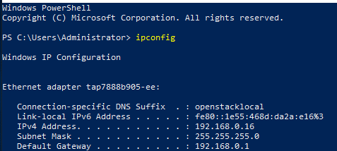
ipconfig
Information similar to the following is displayed. In this example, the Ethernet adapter name is tap7888b905-ee.
- Create a bond group.
- Run the following command to create a bond group for the custom VLAN:
New-NetLbfoTeam -Name <bond-group-name> -TeamMembers "<Ethernet-adapter-name-of-the-network-interface>" -TeamingMode SwitchIndependent -LoadBalancingAlgorithm IPAddresses -Confirm:$false
Variables in the preceding command are as follows:
- bond-group-name: the bond group name of the custom VLAN. In this example, the bond group name is Team1.
- Ethernet-adapter-name-of-the-network-interface: information queried in 3. In this example, the name is tap7888b905-ee.
Example command:
New-NetLbfoTeam -Name Team1 -TeamMembers "tap7888b905-ee" -TeamingMode SwitchIndependent -LoadBalancingAlgorithm IPAddresses -Confirm:$false
Information similar to the following is displayed.

- Run the following commands to query the bond group you have created:
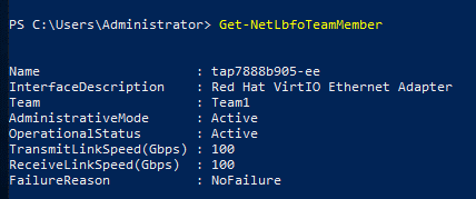
Get-NetLbfoTeamMember
Information similar to the following is displayed.
Get-NetAdapter
Information similar to the following is displayed:

- Run the following command to create a bond group for the custom VLAN:
- Configure a custom VLAN network.
- Run the following command to create a VLAN subinterface:
Add-NetLbfoTeamNIC -Team "<bond-group-name>" -VlanID <VLAN-ID-of-the-supplementary-network-interface> -Confirm:$false
Example command:
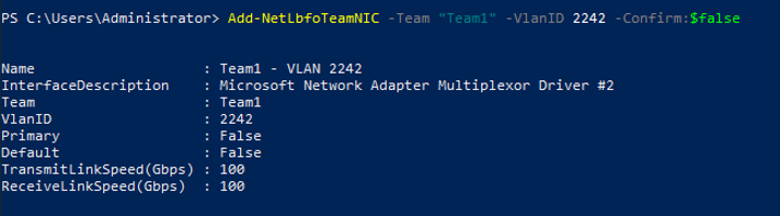
Add-NetLbfoTeamNIC -Team "Team1" -VlanID 2242 -Confirm:$false
Information similar to the following is displayed:
- Run the following command to open the Network Connections page:
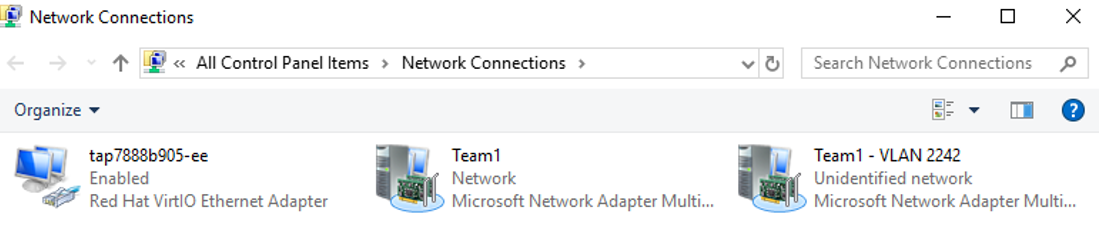
ncpa.cpl
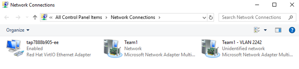
On the displayed page, Team1 is the bond group created in 4.a, and Team1 – VLAN 2242 is the VLAN subinterface created in 5.a.
- Run the following command to create a VLAN subinterface:
- Configure the network for the network interface.
- On the Network Connections page, double-click Team1.
The Team1 Status page is displayed.
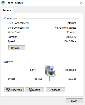
- On the Team1 Status page, click Properties.
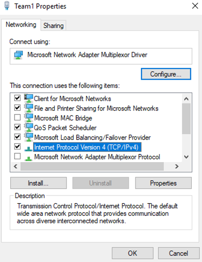
The Team1 Properties page is displayed.
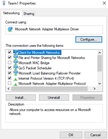
- On the Team1 Properties page, click Configure....
The Microsoft Network Adapter Multiplexor Driver Properties page is displayed.
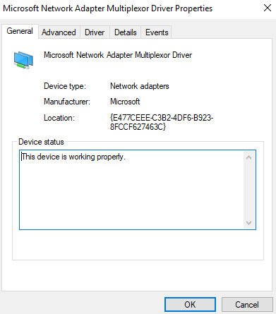
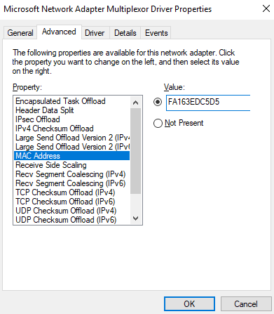
- On the Microsoft Network Adapter Multiplexor Driver Properties page, choose the Advanced tab, click MAC Address, enter the MAC address of the network interface, and click OK.
When entering the MAC address, remove the colons (:) and use the uppercase letters. For example, if the MAC address of the network interface is fa:16:3e:6d:c5:d5, enter FA163E6DC5D5.
- Return to the Team1 Properties page, double-click Internet Protocol Version 4 (TCP/IPv4).
The Internet Protocol Version 4 (TCP/IPv4) Properties page is displayed.

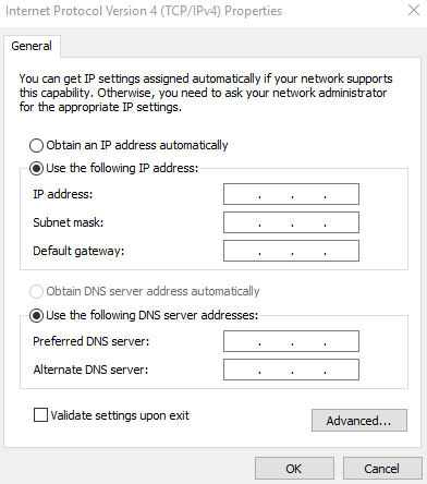
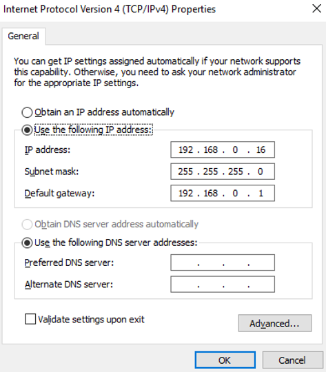
- On the Internet Protocol Version 4 (TCP/IPv4) Properties page, configure the network information of the network interface and click OK.
- Select Use the following IP address:.
- IP address: Enter the private IP address of the network interface. In this example, the private IP address is 192.168.0.16.
- Subnet mask: Enter the mask of the subnet where the network interface is created. In this example, the mask is 255.255.255.0.
- Default gateway: Enter the gateway of the subnet where the network interface is created. In this example, the gateway is 192.168.0.1.
- On the Team1 Properties page, click OK to save the settings.
- Return to the Team1 Status page and click Details....
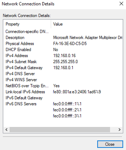
On the Network Connection Details page, check whether the following information is correctly configured:
- Physical Address: MAC address of the network interface.
- IPv4 Address: the private IP address of the network interface.
- IPv4 Subnet Mask: the mask of the subnet where the network interface is created.
- IPv4 Default Gateway: the gateway of the subnet where the network interface is created.
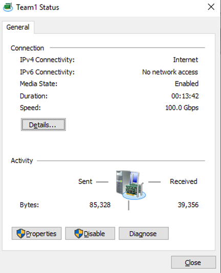
- Check the settings and click Close.
The Network Connections page is displayed.
- On the Network Connections page, double-click Team1.
- Configure the network for the supplementary network interface.
- On the Network Connections page, double-click Team1 - VLAN 2242.
The Team1 - VLAN 2242 Status page is displayed.
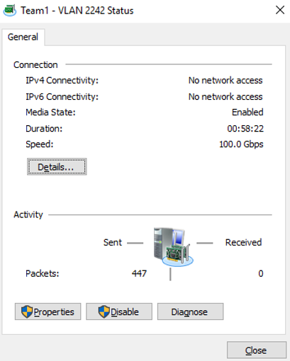
- On the Team1 - VLAN 2242 Status page, click Properties.
The Team1 - VLAN 2242 Properties page is displayed.
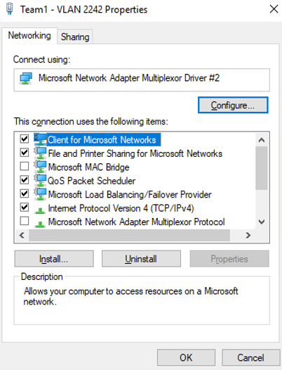
- On the Team1 - VLAN 2242 Properties page, click Configure....
The Microsoft Network Adapter Multiplexor Driver #2 Properties page is displayed.
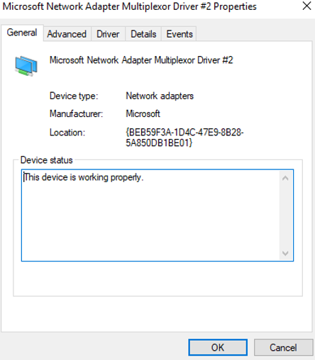
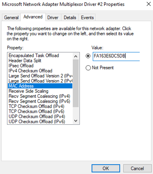
- On the Microsoft Network Adapter Multiplexor Driver #2 Properties page, choose the Advanced tab, click MAC Address, enter the MAC address of the supplementary network interface, and click OK.
When entering the MAC address, remove the colons (:) and use the uppercase letters. For example, if the MAC address of the supplementary network interface is fa:16:3e:6d:c5:db, enter FA163E6DC5DB.
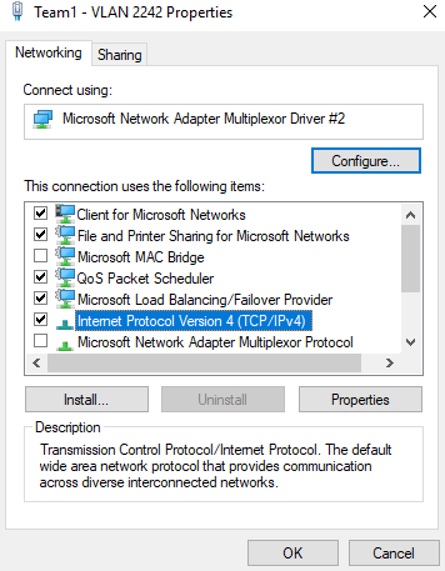
- Return to the Team1 - VLAN 2242 Properties page, double-click Internet Protocol Version 4 (TCP/IPv4).
The Internet Protocol Version 4 (TCP/IPv4) Properties page is displayed.
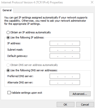
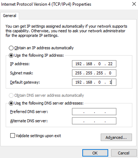
- On the Internet Protocol Version 4 (TCP/IPv4) Properties page, configure the network information of the supplementary network interface and click OK.
- Select Use the following IP address:.
- IP address: Enter the private IP address of the supplementary network interface. In this example, the private IP address is 192.168.0.22.
- Subnet mask: Enter the mask of the subnet where the supplementary network interface is created. In this example, the mask is 255.255.255.0.
- Default gateway: Enter the gateway of the subnet where the supplementary network interface is created. In this example, the gateway is 192.168.0.1.
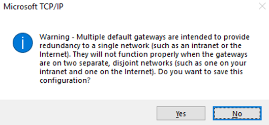
If the following warning is displayed, click Yes to close the dialog box.
- On the Team1 - VLAN 2242 Properties page, click OK to save the settings.

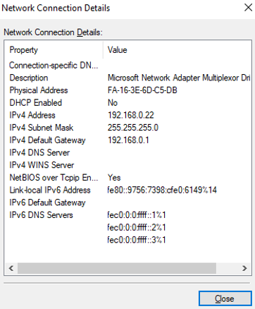
- Return to the Team1 - VLAN 2242 Status page and click Details....
On the Network Connection Details page, check whether the following information is correctly configured:
- Physical Address: MAC address of the supplementary network interface.
- IPv4 Address: the private IP address of the supplementary network interface.
- IPv4 Subnet Mask: the mask of the subnet where the supplementary network interface is created.
- IPv4 Default Gateway: the gateway of the subnet where the supplementary network interface is created.

- Check the settings and click Close.
- On the Network Connections page, double-click Team1 - VLAN 2242.
- On the Windows PowerShell CLI page, check whether the network interface and supplementary network interface are connected to the test ECS.
- Run the following command to verify the connectivity between network interface and the test ECS:
Ping <private-IP-address-of-the-test-ECS> -S <private-IP-address-of-the-network-interface>
Plan the same VPC and security group for the test ECS and the ECS with network interface attached, so that the two ECSs can communicate with each other by default.
Example command:
Ping 192.168.0.133 -S 192.168.0.16
If information similar to the following is displayed, the two ECSs can communicate with each other.

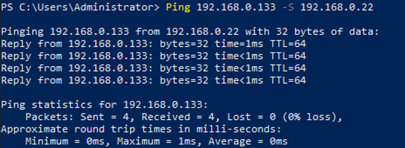
- Run the following command to verify the connectivity between the supplementary network interface of eth0 and the test ECS:
Ping <private-IP-address-of-the-test-ECS> -S <private-IP-address-of-the-supplementary-network-interface>
Plan the same VPC and security group for the test ECS and the ECS with the supplementary network interface attached. This allows the two ECSs to communicate with each other by default.
Example command:
Ping 192.168.0.133 -S 192.168.0.22
If information similar to the following is displayed, the two ECSs can communicate with each other.
- Run the following command to verify the connectivity between network interface and the test ECS: