Model Definition
The VPC network model seamlessly combines VPC routing with the underlying network, making it ideal for high-performance scenarios. However, the maximum number of nodes allowed in a cluster is determined by the VPC route quota. In the VPC network model, container CIDR blocks are separate from node CIDR blocks. To allocate IP addresses to pods running on a node in a cluster, each node in the cluster is allocated with a pod IP range for a fixed number of IP addresses. The VPC network model outperforms the container tunnel network model in terms of performance because it does not have tunnel encapsulation overhead. When the VPC network model is used in a cluster, the routes between container CIDR blocks and VPC CIDR blocks are automatically configured in the VPC route table. This means that pods within the cluster can be accessed directly from cloud servers in the same VPC, even if they are outside the cluster.
Figure 1 VPC network model
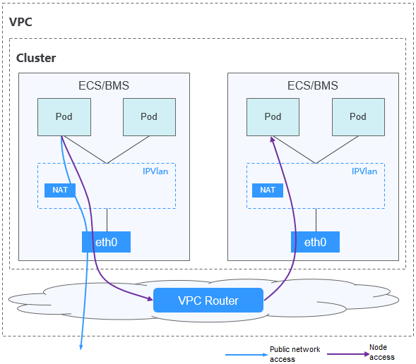
In a cluster using the VPC network model, network communication paths are as follows:
- Inter-pod communication on the same node: Packets are directly forwarded through IPVLAN.
- Inter-pod communication on different nodes: The traffic accesses the default gateway by following the route specified in the VPC route table and then is forwarded to the target pod on another node using VPC routing.
- Pod communication with the Internet: When a container in a cluster needs to access the Internet, CCE uses NAT to translate the pod's IP address into the node IP address so that the pod communicates externally using the node IP address.
Advantages and Disadvantages
Advantages
- High performance and simplified network fault locating are achieved by eliminating the need for tunnel encapsulation.
- A VPC route table automatically configures routes between container CIDR blocks and VPC CIDR blocks. This enables resources in the VPC to directly communicate with containers in the cluster.Note
Similarly, if the VPC is accessible to other VPCs or data centers and the VPC route table includes routes to the container CIDR blocks, resources in other VPCs or data centers can directly communicate with containers in the cluster, provided there are no conflicts between the network CIDR blocks.
Disadvantages
- The number of nodes is limited by the VPC route quota.
- Each node is assigned a CIDR block with a fixed size, which results in IP address wastage in the container CIDR block.
- Pods cannot directly use features like EIPs and security groups.
Application Scenarios
- High performance requirements: As no tunnel encapsulation is required, the VPC network model delivers the performance close to that of a VPC network when compared with the container tunnel network model. Therefore, the VPC network model applies to scenarios that have high requirements on performance, such as AI computing and big data computing.
- Small- and medium-scale networks: Due to the limitation on VPC route tables, it is recommended that the number of nodes in a cluster be less than or equal to 1000.
Pod IP Address Management
A VPC network allocates pod IP addresses based on the rules below. The core rule is to pre-allocate pod CIDR blocks from the container CIDR block to nodes and then allocate IP addresses from the pod CIDR blocks to pods.
- Separate CIDR blocks: The container CIDR block is completely separated from the node CIDR blocks. They do not overlap. This avoids IP address conflicts between nodes and pods. Additionally, these CIDR blocks can be adjusted separately.
- Each node pre-allocated a fixed-size pod CIDR block: A fixed-size pod CIDR block is pre-allocated to each node from the container CIDR block. For example, 128 IP addresses (/25 mask) can be allocated to each node. The CIDR block size can be configured during cluster creation to ensure that each node has sufficient IP addresses for its pods.
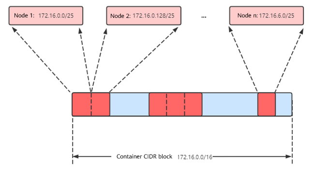
- Each node assigned a pod CIDR block in sequence: When a node is added, a preset-size pod CIDR block is sequentially assigned to it from the container CIDR block. For example, if the container CIDR block is 172.16.0.0/16, then 172.16.0.0/25 is assigned to the first node, 172.16.0.128/25 to the second node, and so on until the container CIDR block is exhausted, as shown in Figure 2.
- Each pod assigned an IP address from the pod CIDR block on the node: After a pod is scheduled to a node, it obtains an IP address from the pod CIDR block pre-allocated to that node in sequence. Pod IP addresses cannot exceed the range of the pod CIDR block on the node.
Figure 2 IP address management of the VPC network
Maximum number of nodes that can be created in the cluster using the VPC network = Number of IP addresses in the container CIDR block/Number of IP addresses in the CIDR block allocated to the node by the container CIDR block
For example, if the container CIDR block is 172.16.0.0/16, the number of IP addresses is 65,536. The mask of the container CIDR block allocated to a node is 25. That is, the number of pod IP addresses on each node is 128. Therefore, a maximum of 512 (65536/128) nodes can be created. The number of nodes that can be added to a cluster is also determined by the available IP addresses in the node subnet and the scale of the cluster. For details, see Recommendation for CIDR Block Planning.
Recommendation for CIDR Block Planning
As explained in Cluster Network Structure, there are three networks in a cluster: cluster network, container network, and Service network. When planning network addresses, consider the following:
- The three CIDR blocks cannot overlap. Otherwise, a conflict occurs.
- Ensure that each CIDR block has sufficient IP addresses.
- The IP addresses in cluster CIDR blocks must match the cluster scale. Otherwise, nodes cannot be created due to insufficient IP addresses.
- The IP addresses in container CIDR blocks must match the service scale. Otherwise, pods cannot be created due to insufficient IP addresses. The number of pods that can be created on each node also depends on other parameter settings.
Assume that a cluster contains 200 nodes and the network model is VPC network.
In this case, the number of available IP addresses in the selected subnet must be greater than 200. Otherwise, nodes cannot be created due to insufficient IP addresses.
The container CIDR block is 172.16.0.0/16, and the number of available IP addresses is 65,536. As described in Pod IP Address Management, the VPC network is allocated a CIDR block with a fixed size (using the mask to determine the maximum number of pod IP addresses allocated to each node). For example, if the upper limit is 128, the cluster supports a maximum of 512 (65536/128) nodes.
Example of VPC Network Access
In this example, a cluster using the VPC network model is created, and the cluster contains one node.
On the VPC console, locate the VPC to which the cluster belongs and check the VPC route table.
You can find that CCE has created a custom route in the route table. This route has a destination address corresponding to the container CIDR block assigned to the node, and the next hop is directed towards the target node. In the example, the container CIDR block for the cluster is 172.16.0.0/16, with 128 pod IP addresses assigned to each node. Therefore, the node's container CIDR block is 172.16.0.0/25, providing a total of 128 pod IP addresses.
When a pod IP address is accessed, the VPC route will forward the traffic to the next-hop node that corresponds to the destination address. The following is an example:
- Use kubectl to access the cluster. For details, see Accessing a Cluster Using kubectl.
- Create a Deployment in the cluster.
Create the deployment.yaml file. The following shows an example:
kind: DeploymentapiVersion: apps/v1metadata:name: examplenamespace: defaultspec:replicas: 4selector:matchLabels:app: exampletemplate:metadata:labels:app: examplespec:containers:- name: container-0image: 'nginx:perl'imagePullSecrets:- name: default-secretCreate the workload.
kubectl apply -f deployment.yaml - Check the running pods.kubectl get pod -owide
Command output:
NAME READY STATUS RESTARTS AGE IP NODE NOMINATED NODE READINESS GATESexample-86b9779494-l8qrw 1/1 Running 0 14s 172.16.0.6 192.168.0.99 <none> <none>example-86b9779494-svs8t 1/1 Running 0 14s 172.16.0.7 192.168.0.99 <none> <none>example-86b9779494-x8kl5 1/1 Running 0 14s 172.16.0.5 192.168.0.99 <none> <none>example-86b9779494-zt627 1/1 Running 0 14s 172.16.0.8 192.168.0.99 <none> <none> - Use a cloud server in the same VPC to directly access a pod's IP address from outside the cluster. You can also access a pod using its IP address within the pod or from a node in the cluster. In the following example, access a pod's IP address within the pod. example-86b9779494-l8qrw is the pod name, and 172.16.0.7 is the pod IP address.kubectl exec -it example-86b9779494-l8qrw -- curl 172.16.0.7
If the following information is displayed, the workload can be accessed:
<!DOCTYPE html><html><head><title>Welcome to nginx!</title><style>body {width: 35em;margin: 0 auto;font-family: Tahoma, Verdana, Arial, sans-serif;}</style></head><body><h1>Welcome to nginx!</h1><p>If you see this page, the nginx web server is successfully installed andworking. Further configuration is required.</p><p>For online documentation and support please refer to<a href="http://nginx.org/">nginx.org</a>.<br/>Commercial support is available at<a href="http://nginx.com/">nginx.com</a>.</p><p><em>Thank you for using nginx.</em></p></body></html>
Helpful Links
- For details about the maximum number of pods that can run on a node in a cluster with different network models, see Maximum Number of Pods That Can Be Created on a Node.